68k project (under construction)
Idea:here
Read by tag:68kavr
Z80 project (considered complete, but will be updated sometimes)
Idea here
Read about Searle Grant's SBC SD interface (and generally CP/M SD implementation) by tag sgsbcsd
Note, that the early records were imported from Livejournal and should be edited by me sometimes later (I bet that will never happen).
Also, some early records may contain some weird letters - that's russian, but it is always translated, do not be afraid.
Also, sometimes I write about some unrelated (even PC!) but weird hardware, some unrelated but weird network technologies, and some weird things. May be even I'll attempt to write a big post about butterflies. If I ever got interested in butterflies.
Showing posts with label 68008. Show all posts
Showing posts with label 68008. Show all posts
Thursday, November 12, 2037

Sunday, December 21, 2014
8Mhz "On Semiconductors" 68008 runs at 12.5Mhz
From several sources I know that Motorola MC68k parts do not like to run on higher freqs then nominal.
At least that's not true for "On Semiconductors" parts.
At least that's not true for "On Semiconductors" parts.
Friday, December 19, 2014
Mathew Brandt's c68 and CP/M 68
While looking for C compiler for CP/M 68 looks I've found something that
looks quite fine.
As for version "5.1 (beta)/25 Apr 2002"
There are a lot of versions of this compiler on the net, but this one is surely the best I've tried (but as I understand it's unable to compile itself, what a pity)
The way it does not work is writing hex as
And you should edit
Next, remember that's just compiler, not even preprocessor: so on unix side I had to do
On CP/M system, assemble the file with
UPD: More, the code it generates can be feed to jas assembler mentioned some time ago.
UPDD: Looks like optimization code is faulty.
UPDDD: 201607 Mirrored Here
As for version "5.1 (beta)/25 Apr 2002"
c68 taken from
http://homepage.ntlworld.com/itimpi/compsrc.htm has -cpm68
option and it somehow work. It even claims that it generates AS68compatible source.There are a lot of versions of this compiler on the net, but this one is surely the best I've tried (but as I understand it's unable to compile itself, what a pity)
The way it does not work is writing hex as
0xXX, not as $XX,
so here is a fix:out68k_c.c:
PRIVATE void put_byte P1 (UVAL,val)
{
    put_header (bytegen, alignment_of_type (tp_char));
    oprintf ("$%lx", (unsigned long) (val & OxffUL));
/*DtZ     oprintf ("0x%lx", (unsigned long) (val & OxffUL)); */
    outcol += 4; /* or  should be changed to +3 ? */
}

PRIVATE void put_word P1 (UVAL, val)
{
   put_header (wordgen, alignment_of_type (tp_short));
/*DtZ     oprintf ("0x%lx", (unsigned long) (val & OxffffUL)); */
    oprintf ("$%lx", (unsigned long) (val & OxffffUL));
    outcol += 6; /* or should be changed to +7? */
}
AS68 does not need/want "\t.sect", it accepts .data and .text directly. out68k_c.c:
static void seg P3 (enum e_sg, segtype, const char *, segname, SIZE, al)
{
 nl();
 if (curseg != segtype) {
/*DtZ   oprintf ("\t.sect\t%s%s", segname, newline);*/
        oprintf ("\t%s * Segment %s", segname, newline);
And you should edit
config.h the way it can generate for 68000 and to check
the compiler binary you get can do -cpm68k and -int=16.
Next, remember that's just compiler, not even preprocessor: so on unix side I had to do
cc -E -I/home/dtz/8BIT/68K/CPM1.3/DISK4 main.c > p_main.c

./cc68 -int=16  -cpm68k -v p_main.c > main.s
Also, note that standard CP/M 68's headers lacks most of the C functions; so I had to copy them
from "C language programming manual" (do not forget to add link link there!)On CP/M system, assemble the file with
AS68 -U file.o, and then link it with CLINK.SUB
UPD: More, the code it generates can be feed to jas assembler mentioned some time ago.
UPDD: Looks like optimization code is faulty.
UPDDD: 201607 Mirrored Here
Tuesday, November 18, 2014
Hello world assember 68k / as68
One more reminder to myself: the skeleton of assembler program
        text
        globl   _main
_main:
        move.b  #'*',d1
        move.w  #2,d0           * calling BDOS '2'
        trap    #2
        move.b  #'*',d1
        move.w  #2,d0           * calling BDOS '2'
        trap    #2
        move.b  #$0A,d1
        move.w  #2,d0           * calling BDOS '2'
        trap    #2
        move.b  #$0D,d1
        move.w  #2,d0           * calling BDOS '2'
        trap    #2
        rts
Assemble
AS68 hello.s
Link
LO68 -R -O hello.68K hello.O
Friday, September 19, 2014
CP/M 68: linking an C and asm file together
I've googled for this stuff for some time, but finished with reading docs. May be that will be usefull for someone else (notibly me when I will look for that once again)
dtzputs.s , implements
test.c ,calls
The next thing to understand is how to get rid of S.O and CLIB, but it is not for today.
dtzputs.s , implements
dtzputs via calling BDOS fn 2
Assemble it withtext globl _dtzputs _dtzputs: move.l 4(sp),a1 *taking argument from stackdtzputsl: move.b (a1)+,d1 *take next char; should if be ANDed with 0x00FF ? A1 expected to be wcmpi.b #0,d1 beq dtzputse move.l a1,-(sp) *storing string pointer to stackmove.w #2,d0 *calling BDOS '2'trap #2 move.l (sp)+,a1 bra dtzputsl dtzputse: rts
AS68 -L -U -S 0: dtzputs.s , get dtzputs.o
test.c ,calls
dtzputs
main()
{
 dtzputs("Fuck a duck");
}
Compile it with C TEST like that:
9C>c test

9C>CP68 -I 0: TEST.C TEST.I

9C>C068 TEST.I TEST.1 TEST.2 TEST.3 -F

9C>ERA TEST.I

9C>C168 TEST.1 TEST.2 TEST.S

9C>ERA TEST.1

9C>ERA TEST.2

9C>AS68 -L -U -S 0: TEST.S

9C>ERA TEST.S

9C>
And link it
9C>clink test dtzputs

9C>LO68 -R -U_NOFLOAT -O TEST.68K 0:S.O TEST.O DTZPUTS.O .O .O .O .O .O .O .O 0:CLIB

9C>test
Fuck a duck
Quack! Quack! Quack!The next thing to understand is how to get rid of S.O and CLIB, but it is not for today.
Tuesday, May 20, 2014
68kavr - considered competed
So that happened.
I consider 68kavr project competed.
That means that it loads OS from SD card
Today I've published my SD card image with the source of BIOS/LDRBIOS, as usuially, here , I'll check two last chapters and copy them there (to be able to discuss them and just they not to be lost one day) in few days.
I consider 68kavr project competed.
That means that it loads OS from SD card
Today I've published my SD card image with the source of BIOS/LDRBIOS, as usuially, here , I'll check two last chapters and copy them there (to be able to discuss them and just they not to be lost one day) in few days.
Thursday, April 24, 2014
68k project: step 7 - CP/M 68, booting from Srecords
Ok, lets start from code. Code for ChVII
The firmware is mostly [or exactly?] the same, but there are two new directories -
The disk image itself contains A: - P: drives, cpmtools with this diskdefs are able to write to A: . Write there a whole CP/M distribution. The disk image comes from Searle Grant's Z80 SBC, (or even my mentioned SD interface for it) as all the DPB stuff.
For the bios reassembly use
Personally I do it with kermit. It's much better for our use then saying minicom.
Here is my kermit initialization (I hope I forgot nothing:)
, it will initialise the card and load something ($2000 bytes?) to somewhere ($1000?). But currently we do not care. Next, load
and
Next, run it via
The next thing is to create
So, the next thing I going to do is to get some text editor. And that will be separate chapter or two.
Some things to mention:
The firmware is mostly [or exactly?] the same, but there are two new directories -
BIOS ,which
contains BIOS (sort of ugly bios), and Disk,
which contains pretty empty disk image and diskdefs for cpmtools.
(local)
The disk image itself contains A: - P: drives, cpmtools with this diskdefs are able to write to A: . Write there a whole CP/M distribution. The disk image comes from Searle Grant's Z80 SBC, (or even my mentioned SD interface for it) as all the DPB stuff.
For the bios reassembly use
assemble script, you'll get bios.s.
Next, load it and CPM15000.SR via cut-and-paste to SBC console.Personally I do it with kermit. It's much better for our use then saying minicom.
Here is my kermit initialization (I hope I forgot nothing:)
set line /dev/ttyS0
set car off
set speed 38400
set flow rts
set transmit timeout 10
(and set input echo on, but I forgot what it is for and if it is really needed)
So from SBC prompt say * boot, it will initialise the card and load something ($2000 bytes?) to somewhere ($1000?). But currently we do not care. Next, load
bios.s and CPM15000.SR by
C-Kermit> transmit CPM15000.SR
and
C-Kermit> transmit bios.s
Next, run it via
go15000 and get A:.
The next thing is to create
CPMLDR and CPM.SYS.
Sure, we will create them on the board. But I refuse to learn CP/M ed!So, the next thing I going to do is to get some text editor. And that will be separate chapter or two.
Some things to mention:
- First, get .68K files from .REL . That's done by series of
RELOCX.SUBscripts - if AS68 says
can't open 0:AS68SYMB.DAT, ensure you have AS68INIT from DISK3 and runAS68 -I AS68INITfor every TPA change -
http://forums.debian.net/viewtopic.php?f=16&t=112244 A very good article how to
recalculate DPBs into cpmtools diskdefs.
It does not help me much because it is long and clever; I always guess some things (and probably wrong)
Monday, April 21, 2014
I have a bootable CP/M 68!
Yes,I did it!
Looks like AS68 has some problems with conditional assembling, so I had to pass my assembler source via linux's cpp. As well it does not like symbols longer then 8 chars (and it's clear why), so using cpp was a good idea (and then transfer it on board).
Anyway, I've got an $18000 TPA. Good!
Looks like AS68 has some problems with conditional assembling, so I had to pass my assembler source via linux's cpp. As well it does not like symbols longer then 8 chars (and it's clear why), so using cpp was a good idea (and then transfer it on board).
Anyway, I've got an $18000 TPA. Good!
Thursday, April 17, 2014
I've burned one more Atmega8A
And found that I have no any Atmega8As till tomorrow. Hopefully this online shop promise to deliver me some chips on next day after an order [in Moscow]; that's good!
I have some Atmega8L's (max 8 Mhz), and tried to make them work at least at 9600.
Ha! It works on 38400! My 68kavr flow control algorithm considered to be good.
I have some Atmega8L's (max 8 Mhz), and tried to make them work at least at 9600.
Ha! It works on 38400! My 68kavr flow control algorithm considered to be good.
Wednesday, April 9, 2014
68k project: step 6 - lets' start thinking about CP/M
First, some news of the project:
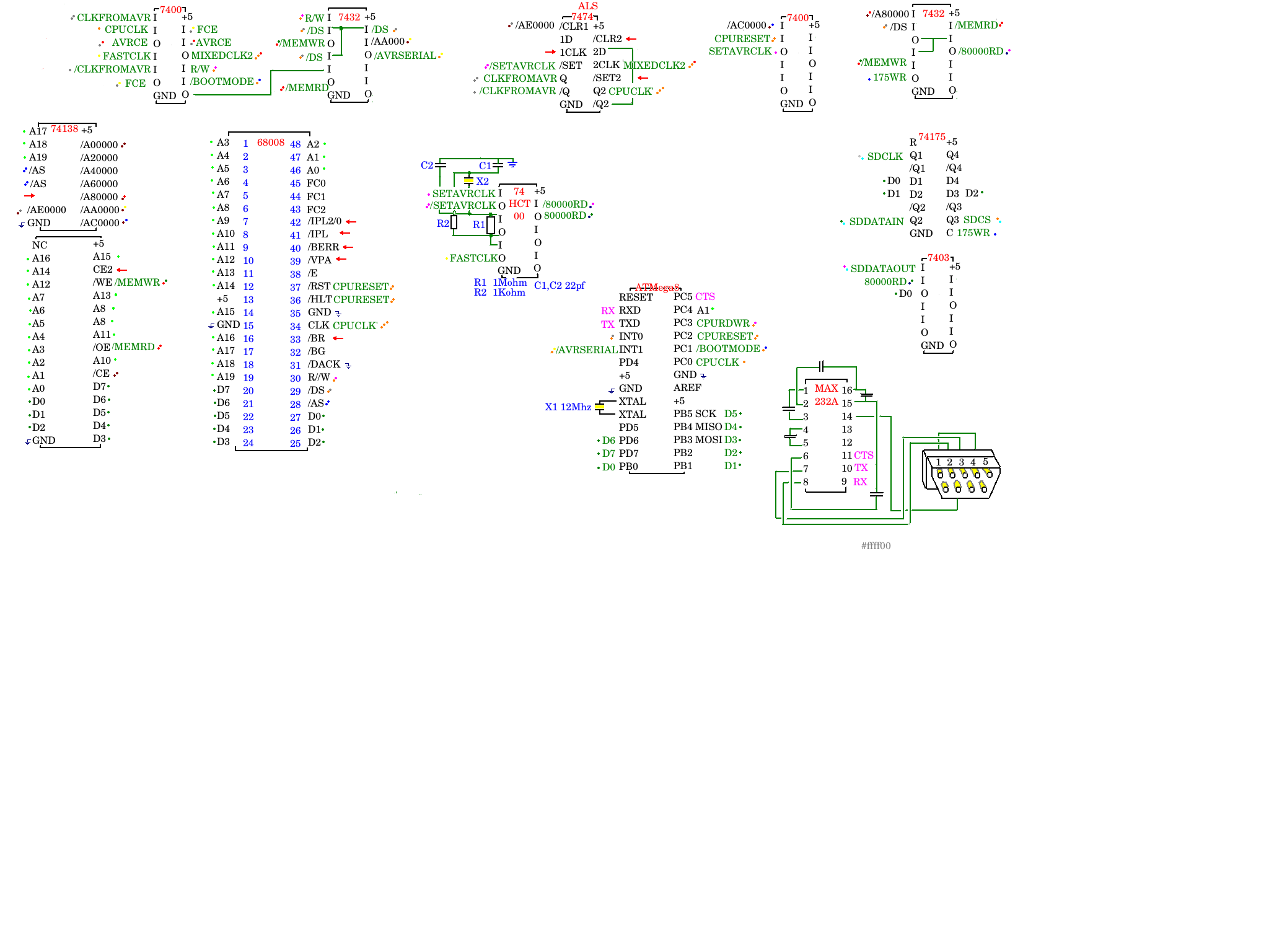
The updated scheme HERE . Generally nothing new, only MAX232A is drawn
 Here is the picture of my board taken 20140325.
First, I have some minor (but nice!) changes in my firmware. First is
And the second... (have I ever told you I'm genius? REALLY? Oh, sorry) - I catch the BREAK from a serial line and inititate CPU Reset! (actually, even MCU reset).
So, in
More, I own an HP 9000 A500 server and it has as "Service Processor". And I'd like to have a full Service Processor console in future like the one on that server. Saying, it can turn on and off ATX power (if I have a spare pin and free memory on Atmega8)....
Sometimes in future
So, let's talk about CP/M iteself
This is my first attempt to port CP/M to any computer by the method explained in, our case, "System Guide". The prerequestings are:
On the first disk of distribution set there is a very useful
So lets go to "System Guide" directly to the Appendix B on page 59 and start type "Sample Bios" into text editor.
As you can see, BIOS install TRAP #3 and CP/M works with BIOS via this TRAP. I've tried to start with
After I wrote basic sector read/write access I was able to say DIR,TYPE and even REN. But could not run any program, that's because I've forgot
That was because I forgot
Funny - this code contains *No* CP/M specific code yet, and is just update of firmware ;-) Code for ChVI
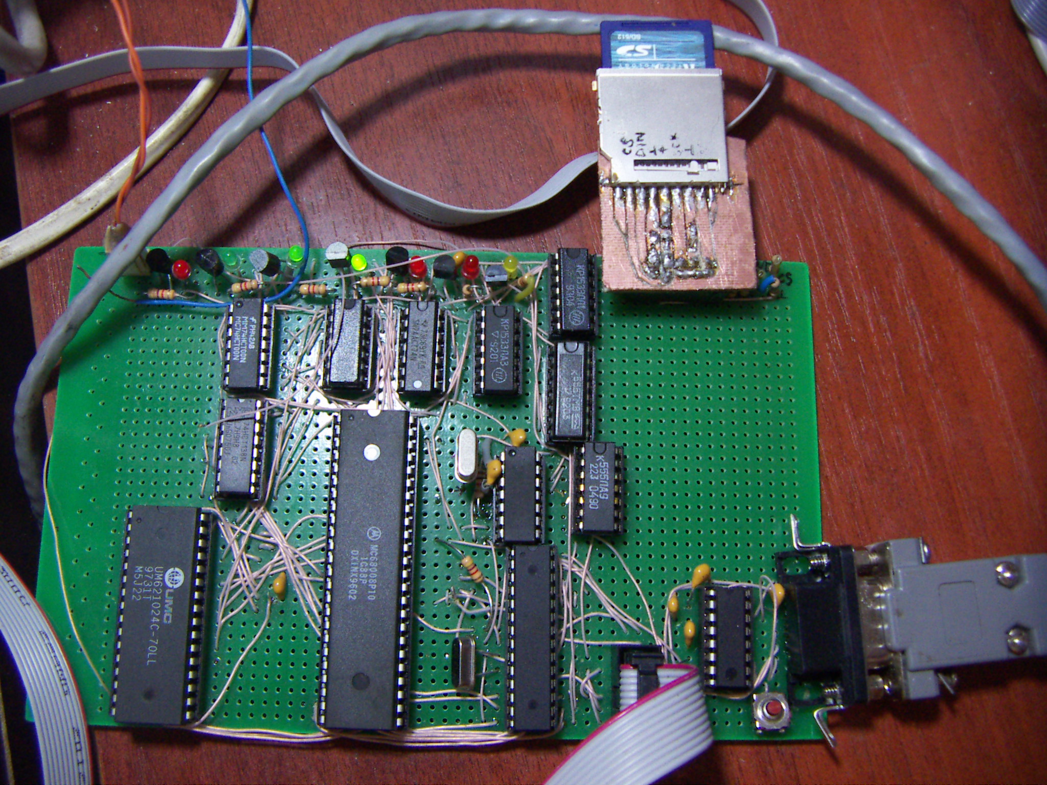 Here is the picture of my board taken 20140325.
 First, I have some minor (but nice!) changes in my firmware. First is
GOaddressmonitor command , which goes to the specified address.And the second... (have I ever told you I'm genius? REALLY? Oh, sorry) - I catch the BREAK from a serial line and inititate CPU Reset! (actually, even MCU reset).
So, in
C-Kermit> (if you use C-Kermit as do I) 's terminal mode, I can press [CTRL]+[\] [B] , and get a reset!More, I own an HP 9000 A500 server and it has as "Service Processor". And I'd like to have a full Service Processor console in future like the one on that server. Saying, it can turn on and off ATX power (if I have a spare pin and free memory on Atmega8)....
Sometimes in future
So, let's talk about CP/M iteself
This is my first attempt to port CP/M to any computer by the method explained in, our case, "System Guide". The prerequestings are:
- I should have System Guide (I do)
- I should have CP/M 68 in S-records (I do from http://www.cpm.z80.de/binary.html : I use this)
- The system must accept S-Records (my does)
- I must have an assembler which generates S-Records (I use A68k from TI 68K calculator project:
Warning: do not use asm68k68000 Assembler - version 2.71.F3s (Sep 21, 2004) Copyright 1985 by Brian R. Anderson AmigaDOS conversion copyright 1991 by Charlie Gibbs. Adapted for use with Fargo by David Ellsworth. Bugfixes and additions by Julien Muchembled, Paul Froissart and Kevin Kofler
buggy as shit. May be vasm is good - but I'm not ready to write linker scripts just to get SRecord from the source with static lables and given ORG)asmx multi-assembler version 2.0b5 Copyright 1998-2007 Bruce Tomlin
CPM15000.SR - that's an CP/M in S-Records (which is loaded from address $15000).On the first disk of distribution set there is a very useful
README.TXT which says that to create a BIOS I should figure out
_init (== ORG of BIOS == $1B000) and _ccp ($150BC) symbols in CPM15000.MAP (and that differs from what is written in "System Guide";
there said you should patch Srecords file [for 1.0 and 1.1 CP/M 68k vers.]).So lets go to "System Guide" directly to the Appendix B on page 59 and start type "Sample Bios" into text editor.
As you can see, BIOS install TRAP #3 and CP/M works with BIOS via this TRAP. I've tried to start with
- constat
- conin
- conout
setexc also a must for CP/M to show you it's A:>. The first thing it does, it installs an TRAP handlers for almost all the TRAPS!
I will not retype it here, that will be attached later, when it will be at least read/write sectors.
To start CP/M first load CP/M itself, then BIOS, then type go15000After I wrote basic sector read/write access I was able to say DIR,TYPE and even REN. But could not run any program, that's because I've forgot
getseg call at all. And then I was able to run DDT68000,
but during read it compained "Cannot write sector" (and it was not writing sector at all!)That was because I forgot
flush call.Funny - this code contains *No* CP/M specific code yet, and is just update of firmware ;-) Code for ChVI
Tuesday, April 8, 2014
Looking for text editor for CP/M 68K
So, I have plain 68K system where I can CP/M by loading it via SRecords.
I want to build CPMLDR & CPM.SYS, so I want to edit them on board to assemble and link. Edit means editor, and I refuse to understand how cp/m's ED work.
So I want to compile some editor, what's the simpliest? Edlin, for sure.
So we have:
So currenlty I'm trying to compile them, or find some other edlin clone. I know that MicroEmacs/CP/M-68K exists, that's an apportunity, too.
I want to build CPMLDR & CPM.SYS, so I want to edit them on board to assemble and link. Edit means editor, and I refuse to understand how cp/m's ED work.
So I want to compile some editor, what's the simpliest? Edlin, for sure.
So we have:
- FreeDOS's edlin
- Terry McConnell's deadlin
fgetpos, which CP/M 68K's compiler lacks.
FreeDOS's edlin is more complicated.So currenlty I'm trying to compile them, or find some other edlin clone. I know that MicroEmacs/CP/M-68K exists, that's an apportunity, too.
Thursday, March 20, 2014
68k project: step 5 - SD interface
The idea of SD interface is just an adoptation of my SD interface for Searle's Grant SBC. So go there for SD card pinout,resistor values, 3.3V power, etc. The only change is 2*7474 to one 74175. Or you can use 2*7474. Or any latch of this sort.
Some notes: a rewiring /AC0000,CPURESET->SETAVRCLK, FCE,AVRCE->MIXEDCLK2 on the scheme is not significant at all and is here just to correspond my actual wiring.
As for SD interface, it consists of a 74175 trigger for data output and 7403 as data input. To write to 74175 we mix /A80000 line with /MEMWR and /DS (on an extra 7432) and latch D0-D2 to the trigger, so that are SD card's Clock (SDCLK), DataIn (SDDATAIN) and Chip Select (SCCS) [why SCCS? Rename it to SDSC later] SPI lines. They should be mixed via resistors to get 3.3V-alike signals (again, see this). Do not forget that SD card itself should be feed with +2.8 - +3.3V so you can use 7833 or just a LED to drop the voltage.
For data in, we mix /A80000 line with /MEMRD and /DS to get /80000RD and invert it to get 80000RD. Passed throw 7403 (with SDDATAOUT) we direct this open-collecor output to D0. So this output is low only when 80000RD is active (high) and SDDATAOUT is high too, so this is inverted input. So, from 68k side we can
    move.b #7,$80000 ; CS - up, Dataout - up, CLK - up
    move.b #2,$80000 ; CS - down, Dataout - up, CLK - down
manage that bits this way (but better keep higher bits high - we may have some extra SPI devices in future), and
to read it just read lower bit from $80000 and invert it.Just to remind:
D0 - CLK
D1 - DATAOUT
D2 - CS
D3 and D4-D7 - reserved for future SPI devices (who knows which? extra Atmega, RTC, etc)

The Code for ChV can detect (command "BOOT") the card (CMD0), can send it CMD1 for (doing smth usefull), some command to ensure the card's sector size is 512 bytes, but nothing more still. (I use this and this) as reference)
Also, scince now I use Atmega's PC5 pin for CTS. That's because I've tried to cut-and-paste CP/M-68 S-record files and was unable to do that without hardware flow. So in AVR code there is a #define WITH_CTS to use this code (enabled by default) and 256 bytes ring boofer for handling input bytes from serial.
As you could note, there is a sort-of-monitor program included in 68k asm Currently it can:
BF Blink SDCLK fast (with fullspeed clock)BS Blink SDCLK slow (with AVRCLK)BLINK Blink until key pressed (fullspeed clock)ON Set SDCLK to 0 (or 1)OFF Set SDCLK to 0 (or 1)1 Set SDCLK to 1, SDDATAIN to 0, SCCS to 0)2 Set SDCLK to 0, SDDATAIN to 1, SCCS to 0)4 Set SDCLK to 0, SDDATAIN to 0, SCCS to 1)IN Tell SDDATAOUT status (or inverted SDDATAOUT?)DUMP[optional address] Dump memory from address (or continue to dump from that address if no address given)BOOT Try to init the SD cardS[srecord] Parce S-Records. It understands S1,S2,S3 records and ignores all the othersIt's easy to extend this command set:
first, write an f_myfunc subrotine which should return to monotor with rts. Then add it's mnemonic to commands: and it's address (f_myfunc) to commands_vector When called, A1 will point to the first byte after you's command mnemonic in input buffer, so if was called as
myfuncbebebe
, A1 will point to "bebebe"
:Also there is one more thing I want to warn you: I use ISP programming of ATmega via SCLK/MOSI/MISO/RESET pins of ATmega, AND THIS IS UNRELATED TO SPI BUS WE'VE JUST DISCUSSED!
: Be careful: I've burned 3 Atmega's while ISP programming it until I installed a RESET switch for CPU (RESET+HALT)
So to make an ISP firmware update, hold down RESET+HALT of CPU, then do firmware update (I use avrdude and usbasp)
Wednesday, February 26, 2014
68k project: step IV - Switching to fast clock
[original article - http://xepb.org/dtz/68kavr.html ]
20140129
We will add fast clock. Just will, because out current CPU clock is slow. And for future 68681 UART which I am planning.
On my opinion, our AVR clock is about 60 times slower then external clock. (I run ATmega8A from 12Mhz crystal).
So lets' add an external quarts. (around 12 in my case; it will be devided by 2, read more). We will use
the Searle Grant's scheme on 74HCT04 and get FASTCLK signal pins 3,4,5,6.
And a trigger - 7474 (should be ALS or HCT, but I've tried old 7474 and it worked too.)
The trigger (1-7 pin) will behave the following manner: on reset, it will be at 1 (CLKFROMAVR high), and
by accessing E0000 address it will go low, that will be switching to fast clock. Also, by accessing C0000
from CPU you can switch it back to AVR clock. So we will mix /C0000 and /CPURESET signals on 7400, so
it will go high when any of /CPURESET and /C0000 will be active, and invert it on 74HCT00 pins 0 and 1
Then, we'll take the trigger output (CLOCKFROMAVR and /CLOCKFROMAVR) and mix it with CPUCLK on one segment
of 7400 and with FASTCLK. We'll get AVRCE (AVR Clock Enabled) and FCE (Fast Clock Enabled) signals.
When any of them disabled, it will go high, the other should tick. And let's mix them on one extra 7400
to get MIXEDCLK2
Is MIXEDCLK2 is good for clocking CPU? Maybe, I'm not sure.
Imagine you switch from AVR clock by accessing E0000, and fast clock front comes right after that?
That may be not good (because that will lead to a very fast clock tick) (or may not, because when you
switch the trigger you are at the end of cycle)
So let's use the other side of the moon 7474 trigger it to revert on any even clock change.
(And this devides clock by two.) I do not remember why I've decided that, but I really thought we'll have
one guaranteed tick in the worst case; it looks I'm wrong.
Anyway, this works ;-) (it really was an argument of doing it, but I forgot)
And unsolder CPUCLK clock from CPU and connect it to the output of that trigger (called CPUCLK')
20140213 Well, here it the worst case this trigger prevents: imagine we switch the clock
from slow to fast, and the MIXEDCLK2 is high. And saying when switched to fast clock it's low and
just before rising edge. So, the MIXEDCLK2 will go from high (from AVR) to low and back to high
too fast.
This is the case this trigger prevents.

We've never discussed M68K assembler code; some code in examples, but now it's time to speak about it
Currently I use A68K assembler (not pila) to get binary output of program; it has $1D bytes prefix (is it
for HP calc?), so I cut it and translate the rest of binary to C code via bin2c.tcl script.
While what you see in the 68K code is very experimetal (this is my first attempt to write 68K code),
at least here you can see an example (in byteio_fast.asm) file how to read and write bytes via AVR UART emulation
20140129
We will add fast clock. Just will, because out current CPU clock is slow. And for future 68681 UART which I am planning.
On my opinion, our AVR clock is about 60 times slower then external clock. (I run ATmega8A from 12Mhz crystal).
So lets' add an external quarts. (around 12 in my case; it will be devided by 2, read more). We will use
the Searle Grant's scheme on 74HCT04 and get FASTCLK signal pins 3,4,5,6.
And a trigger - 7474 (should be ALS or HCT, but I've tried old 7474 and it worked too.)
The trigger (1-7 pin) will behave the following manner: on reset, it will be at 1 (CLKFROMAVR high), and
by accessing E0000 address it will go low, that will be switching to fast clock. Also, by accessing C0000
from CPU you can switch it back to AVR clock. So we will mix /C0000 and /CPURESET signals on 7400, so
it will go high when any of /CPURESET and /C0000 will be active, and invert it on 74HCT00 pins 0 and 1
Then, we'll take the trigger output (CLOCKFROMAVR and /CLOCKFROMAVR) and mix it with CPUCLK on one segment
of 7400 and with FASTCLK. We'll get AVRCE (AVR Clock Enabled) and FCE (Fast Clock Enabled) signals.
When any of them disabled, it will go high, the other should tick. And let's mix them on one extra 7400
to get MIXEDCLK2
Is MIXEDCLK2 is good for clocking CPU? Maybe, I'm not sure.
Imagine you switch from AVR clock by accessing E0000, and fast clock front comes right after that?
That may be not good (because that will lead to a very fast clock tick) (or may not, because when you
switch the trigger you are at the end of cycle)
So let's use the other side of the moon 7474 trigger it to revert on any even clock change.
(And this devides clock by two.) I do not remember why I've decided that, but I really thought we'll have
one guaranteed tick in the worst case; it looks I'm wrong.
Anyway, this works ;-) (it really was an argument of doing it, but I forgot)
And unsolder CPUCLK clock from CPU and connect it to the output of that trigger (called CPUCLK')
20140213 Well, here it the worst case this trigger prevents: imagine we switch the clock
from slow to fast, and the MIXEDCLK2 is high. And saying when switched to fast clock it's low and
just before rising edge. So, the MIXEDCLK2 will go from high (from AVR) to low and back to high
too fast.
This is the case this trigger prevents.
We've never discussed M68K assembler code; some code in examples, but now it's time to speak about it
Currently I use A68K assembler (not pila) to get binary output of program; it has $1D bytes prefix (is it
for HP calc?), so I cut it and translate the rest of binary to C code via bin2c.tcl script.
While what you see in the 68K code is very experimetal (this is my first attempt to write 68K code),
at least here you can see an example (in byteio_fast.asm) file how to read and write bytes via AVR UART emulation
uartstat equ $A0002
uartdata equ $A0000
slowclock equ   $C0000
fastclock equ   $E0000

;------------------ RX char
rx_char:
    bsr rx_notempt      ; while rx is not empty, ie, no char
    beq rx_char         ; loop
    move.b      d0,(slowclock) ; switching clock slow
    move.b      (uartdata),d0   ; read from uart
    move.b      d0,(fastclock) ; switching clock fast
    cmpi.b      #CTRLC,d0       ; CTRL-C?
    beq warm    ; warm reset
    rts

;------------------ Test input for a char (NOT ZERO if IS)
rx_notempt:
    move.b      d0,(slowclock) ; switching clock slow
    move.b      (uartstat),d0
    move.b      d0,(fastclock) ; switching clock fast
    andi.b      #$02,d0 ; bit 1 is 1? (I've told you that it is my first attempt to write 68k code!)
    rts

;------------------ Wait for clear to send -------
tx_rdy_w:
    move.l      d0,-(sp)
tx_rdy_w1:
    bsr tx_rdy
    bne tx_rdy_w1
    move.l      (sp)+,d0
    rts

;------------------ TX char
tx_char:
    bsr tx_rdy_w
    move.b      d0,(slowclock) ; switching clock slow
    move.b      d0,(uartdata)
    move.b      d0,(fastclock) ; switching clock fast
    rts
;----------------- Returns TX ready (Z)
tx_rdy:
    move.b      d0,(slowclock) ; switching clock slow
    move.b      (uartstat),d0
    move.b      d0,(fastclock) ; switching clock fast
    andi.b      #$01,d0
    rts


The most interesting in this code is that it is working. I do not know what to tell you about this code,
may be the only thing: do not forget to switch the clock fast in your's main program

 Avr/GCC/A86k source code
Thursday, January 16, 2014
68k project: step III - execute some bytes by 68008 from RAM
[original article - http://xepb.org/dtz/68kavr.html ]
Well, to run program from RAM we should solder it in.
So, the Scheme 2:

So here will be an algorythm (bold is new code):
, then, in loop,
, replacing zeroes by the bytes from the actual program. The trailing NOP is needed because 68008 prefetches one command before executing the prevous (as shown in Chapter II)
And hereare the tits is current photo of my board (20140118)

K1533LA3 = 74ALS00, K1533LL1 = 74ALS32, K555ID7 == 74LS138 (Soviet/russian chips)
The GCC source of AVR program for chapter III
Well, to run program from RAM we should solder it in.
So, the Scheme 2:
First, note the 74138. It decodes higher adress lines. It's all clear with it. Also, that it clear that RAM should start on Addr 0h, so put the /A0000 line to /CE of RAM.
Look at Atmega. The most significant of the new connections is the /BOOTMODE line. It is used to inform RAM to behave the following way: when /BOOTMODE is active, CPU should read not from RAM, but from MCU. It is AND-NOTed with R/W, so when /BOOTMODE is active (0) and READ(1) happens, the output of 7400 leg 8 is not active (high). When /BOOTMODE is not active and READ goes high, the output of 7400/8 goes low, and, ORed with /DS, this is fed (as /MEMRD) to /OE pin of RAM.
7432 also ORs /DS and R//W to get /MEMWR.
Sure, we'll use ATmega as uart, so we should connect one of the lines from 74138 ORed with DS to one of ATmega's leg (again, as interrupt, while that's not absolutely needed). And add an address line (A1) to get two registers for read and for write.
It's all clear that one pair is read byte from line and write byte to line, the other read register is status saying "we have an byte in input" and "it's clear to send the next char". The extra writing register is a HEX output.
So here will be an algorythm (bold is new code):
/* Interrupt handling - DS gone low */
void ISR0()
{
 if (RWline is UP) {
 /* feed a byte to CPU */
  writing_on_bus = 1;
  b = bytefeeder();
  if (b != -1)
  {
   write_on_bus(b);
  } else { // The boot 68k program is ended!
   bootmode = 0; /* and /BOOTMODE leg*/
   reset_CPU();
   /*optional*/ uninstall_IRQ_0_handler();
  }
 } else {
 /* CPU is writing byte to memory*/
 }
}

void ISR2(USART_RXC_vect) // Serial event: a char came from terminal to AVR
{
 byte_came = byte_from_serial();
 byte_in_rx_que = 0x02; // Flag to be ORed when we'll tell CPU the status
}

void ISR1() // interrupt happened on /AVRSERAIL goes low
{
 if (RWline is UP)
 {
 /* CPU is reading from serial */
  writing_on_bus = 1;
  if (A2_line_is_up) // CPU reads status
  {
   write_on_bus (clear_to_send | byte_in_rx_que);
  } else
  {
   write_on_bus(byte_came); // last recieved byte from serial
   byte_in_rx_que = 0;
  }
 } else  /*CPU is writing to bus*/
 {
  if (A2_line_is_up)
  {
   serial_send_hex(byte_from_data_bus());
  } else
  {
   serial_send(byte_from_data_bus());
  }
 }
}


void main()
{
 bootmode = 1; /* as well as /BOOTMODE leg */
 byte_in_rx_que = 0; // No pending serial bytes
 reset_CPU(); reset_ticks = RESET_TICKS_VAL;
 install_int0_handler(DS_line_does_down);
 install_int1_handler(AVRSERIAL_goes_down); // Both can be done when leaving bootmode
 install_serial_rx_handler();
 while(1)
 {
  click_clock();
  if (reset_ticks > 0)
  {
   if (!(reset_ticks--))
   {
    release_reset_CPU(); // reset - up!
   }
  }
  if (DS_line_got_high)
  {
   if (writing_on_bus) {
    switch_data_bus_to_read_mode();
    writing_on_bus = 0;
   }
  }
 }

}
What do we feed to cpu, you may ask?
Here it is (in file bytefeeder.c):
uint8_t PROGMEM prologue[] = {
  0x00,0x00,0x10,0x00  // 0       dc.l stack pointer
  ,0x00,0x00,0x00,0x08 // 0       dc.l start
  ,0x20,0x7C ,0x00,0x00,0x00,0x00 // 8       movea.l #0,A0
};
, then, in loop,
uint8_t PROGMEM program_loop_bytes[] = {
 0x30, 0xFC, 0, 0, // move.w #XX,(A0)+
 0x4e, 0x71 // NOP
};
, replacing zeroes by the bytes from the actual program. The trailing NOP is needed because 68008 prefetches one command before executing the prevous (as shown in Chapter II)
And here
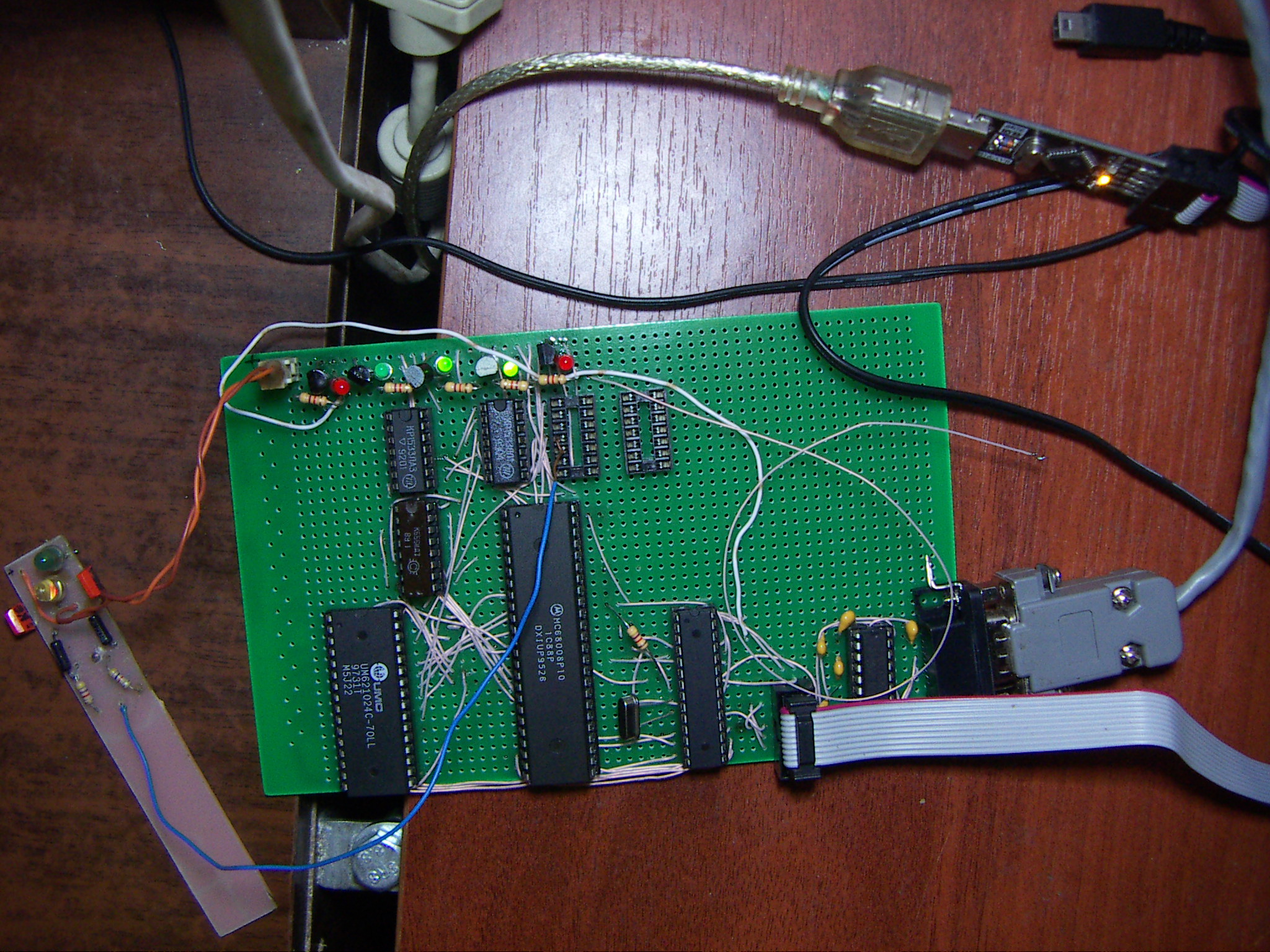
K1533LA3 = 74ALS00, K1533LL1 = 74ALS32, K555ID7 == 74LS138 (Soviet/russian chips)
The GCC source of AVR program for chapter III
68k project: step II - execute some bytes by 68008 taken from AVR, actually!
[original article - http://xepb.org/dtz/68kavr.html ]
The scheme for Running first program

The GCC source or AVR program
The result of running program:
So, we see that at least one command was executed by CPU
The scheme for Running first program
The GCC source or AVR program
The result of running program:
(* is a clock tick , is a comment)
************************************************************************************************************************************
********************************************************************************************
 Calling release reset
[Released reset]
**************************** clock after reset
INT: R         Int happens when /DS goes low; R means that CPU is READING
State 0000*****     "State 00" is some debug message, the other byte is actual byte
Releasing bus***   5 clock changes /DS from low to high; 'Releasing bus' - MCU put data bus to high impedance.
INT: R
State 0000*****
Releasing bus***
INT: R
State 0000*****
Releasing bus***
INT: R
State 0008*****    fed with 00000008; really the address does not matter, but it must be even, as you understand  ;-) -
Releasing bus***  the first thing I've got was a trap leading write 14 bytes to somewhere
INT: R
State 0000*****
Releasing bus***
INT: R
State 0000*****
Releasing bus***
INT: R
State 0000*****
Releasing bus***
INT: R
State 00C0*****  fed by stack pointer
Releasing bus***
INT: R
State 0020*****
Releasing bus***
INT: R
State 007C*****
Releasing bus*******
INT: R
State 0000*****
Releasing bus***
INT: R
State 0000*****
Releasing bus***
INT: R
State 0000*****
Releasing bus***
INT: R
State 0000*****       fed with movea.l #0,A0
Releasing bus***
INT: R
State 0020*****
Releasing bus***
INT: R
State 003C*****
Releasing bus***
INT: R
State 00AA*****
Releasing bus***
INT: R
State 0055*****
Releasing bus***
INT: R
State 0033*****
Releasing bus***
INT: R
State 00CC*****   fed with move.l #$aa5533cc,D0
Releasing bus***
INT: R
State 0020*****
Releasing bus***
INT: R
State 0080*****     move.l D0,(A0)
Releasing bus***
INT: R
State 004E*****
Releasing bus***
INT: R
State 0071*****  fed with NOP - that's prefetching
Releasing bus*****
INT: WAA********  Writing data! Whuuuuaaaaaauhuhhhh!
INT: W55********
INT: W33********
INT: WCC******
INT: R
State 004E*****
Releasing bus***
INT: R
State 0071*****
Releasing bus***
INT: R
State .....
So, we see that at least one command was executed by CPU
68k project: step I - execute some bytes by 68008 taken from AVR - the theory
[original article - http://xepb.org/dtz/68kavr.html ]
Getting Reset, AVR (MCU) lowers RESET+HALT of 68008 (CPU) and begins to click clocks in main loop, which leads to the state called Boot Mode, and raises CPU's RESET+HALT some clicks after that.
Getting falling font of DS the MCU's INT0 is accured; while serving INT, main program waits until INT0 finished, so clock does not click, and there is no reason to play DTACK
INT0 feeds next byte of program to the CPU data bus (if CPU reads it), and leaves it there, returning from INT0 hanlder and making the main clock clicks. When main loop detects that DS is not active, it removes data from data bus.
So here it is:
While in boot mode, CPU should transfer some initial program to to memory,
then MCU should leave boot mode and send reset. After reset, CPU should execute the
main program already in RAM. It can later switch the clock source to run from a fast quartz.
2014016
Note 1. We have serial on ATmega, and you can use MAX232 or whatever you like
to connect it to COM port or USB.
Note 2. It is mentioned that interrups are used to determine /DS signal. Generally,
you do not need that because while CPU is clocked from MCU they are fully syncronized
(and when CPU will be clocked from external source there will be no way to talk with MCU
because it is slow). AVR interrupts are used because the code is clearer.
Getting falling font of DS the MCU's INT0 is accured; while serving INT, main program waits until INT0 finished, so clock does not click, and there is no reason to play DTACK
INT0 feeds next byte of program to the CPU data bus (if CPU reads it), and leaves it there, returning from INT0 hanlder and making the main clock clicks. When main loop detects that DS is not active, it removes data from data bus.
So here it is:
/* Interrupt handling - DS gone low */
void ISR0()
{
 if (RWline is UP) {
 /* feed a byte to CPU */
  writing_on_bus = 1;
  write_on_bus(bytefeeder());
 } else {
 /* CPU is writing byte */
 }
}


void main()
{
 bootmode = 1;
 reset_CPU(); reset_ticks = RESET_TICKS_VAL;
 install_int0_handler(DS_line_does_down);
 while(1)
 {
  click_clock();
  /* may be some minimal delay, but CPU should be much faster then MCU*/
  if (reset_ticks > 0)
  {
   if (!(reset_ticks--))
   {
    release_reset_CPU(); // reset - up!
   }
  }
  if (DS_line_got_high)
  {
   if (writing_on_bus) {
    switch_data_bus_to_read_mode();
    writing_on_bus = 0;
   }
  }
 }

}
While in boot mode, CPU should transfer some initial program to to memory,
then MCU should leave boot mode and send reset. After reset, CPU should execute the
main program already in RAM. It can later switch the clock source to run from a fast quartz.
2014016
Note 1. We have serial on ATmega, and you can use MAX232 or whatever you like
to connect it to COM port or USB.
Note 2. It is mentioned that interrups are used to determine /DS signal. Generally,
you do not need that because while CPU is clocked from MCU they are fully syncronized
(and when CPU will be clocked from external source there will be no way to talk with MCU
because it is slow). AVR interrupts are used because the code is clearer.
Monday, October 21, 2013
Launching 68k project
So Z80 project is considered completed.
I'm not going to stop poking the soldering iron to Z80, for sure, but now I want to implement 68k project.
The idea is mostly the same.
We'll boot it from AVR, sure ;-)
AVR will also always click the clocks (for stage 1) and serve as UART (for stage 1 and 2)
This is the start of desiging.
Stage 1: chips: AVR (Atmega8, I suppose, CPU (68008), SRAM chip), DTACK grounded
Stage 2: same with external quartz and the ability of cpu to turn on external quartz or switch back to AVR clock. This will be needed when we use AVR as UART. So before accessing AVR, we'll switch to AVR clock, write/read AVR, switch to fast clock.
No need to use DTACK.
SPI port. SD card.
Stage 3: same with external UART. DTACK will be grounded always except external UART accessing. So some BGERR logic is planned.
MMU is not planned, so the best I'll be able to run here is CP/M 68, not NetBSD.

[UPD error: R//W line should be inverted before going to OR to atmega; it should catch /Reads, not /Writes]
The first stage and booting logic follows:
Main program for avr -
- Hold down RESET & HALT lines, click the clock for some time.
- clock the clk line. If we have data on data line and /DS got high, put data in hi-impedance mode.
On RESET, Trigger should set 0 on Q line [/BOOTMODE], and in every read access to 0-1FFFF it will generate an INT0 on avr.
Getting the interrupt, AVR will put the byte data from the program to data line:
LEA $800,A0
LOOP: MOVE.B #$BYTE_FROM_A_PROGRAM_TO_BE_BOOTED,(A0+)
BRA LOOP
BRA $800 (and turn off the boot mode!)
(or like that)
and pausing for clicking clock until interrupt ends.
While beeing in BOOTMODE (and Q is not active) if we /write anything to 0-1FFFF the data will go to RAM. And when the bootmode ends, every access to the 0-1FFFF will go there.
Accessing D0000 - FFFFF from CPU will end boot mode. Really, now it's not clear to me should boot mode be terminated by CPU or AVR. [UPD 20140313 Later this idea was significantly simpified]
I'm not going to stop poking the soldering iron to Z80, for sure, but now I want to implement 68k project.
The idea is mostly the same.
We'll boot it from AVR, sure ;-)
AVR will also always click the clocks (for stage 1) and serve as UART (for stage 1 and 2)
This is the start of desiging.
Stage 1: chips: AVR (Atmega8, I suppose, CPU (68008), SRAM chip), DTACK grounded
Stage 2: same with external quartz and the ability of cpu to turn on external quartz or switch back to AVR clock. This will be needed when we use AVR as UART. So before accessing AVR, we'll switch to AVR clock, write/read AVR, switch to fast clock.
No need to use DTACK.
SPI port. SD card.
Stage 3: same with external UART. DTACK will be grounded always except external UART accessing. So some BGERR logic is planned.
MMU is not planned, so the best I'll be able to run here is CP/M 68, not NetBSD.
[UPD error: R//W line should be inverted before going to OR to atmega; it should catch /Reads, not /Writes]
The first stage and booting logic follows:
Main program for avr -
- Hold down RESET & HALT lines, click the clock for some time.
- clock the clk line. If we have data on data line and /DS got high, put data in hi-impedance mode.
On RESET, Trigger should set 0 on Q line [/BOOTMODE], and in every read access to 0-1FFFF it will generate an INT0 on avr.
Getting the interrupt, AVR will put the byte data from the program to data line:
LEA $800,A0
LOOP: MOVE.B #$BYTE_FROM_A_PROGRAM_TO_BE_BOOTED,(A0+)
BRA LOOP
BRA $800 (and turn off the boot mode!)
(or like that)
and pausing for clicking clock until interrupt ends.
While beeing in BOOTMODE (and Q is not active) if we /write anything to 0-1FFFF the data will go to RAM. And when the bootmode ends, every access to the 0-1FFFF will go there.
Accessing D0000 - FFFFF from CPU will end boot mode. Really, now it's not clear to me should boot mode be terminated by CPU or AVR. [UPD 20140313 Later this idea was significantly simpified]
Subscribe to:
Posts (Atom)